Internet Educational Series #2: IP Basics
How does the Internet work? If you ever had this question popping up in your head, you’ve landed in the right place. In today’s article…

How does the Internet work? If you ever had this question popping up in your head, you’ve landed in the right place. In today’s article, we will talk about Internet Protocol (IP).
Hello dear reader! And welcome to my Internet Educational Series.
Here you’ll learn all the basics from the Internet, how does it work, why does it work, the protocols used, and many more you’ll discover as you read through my articles.
I hope you like them, and enjoy them as much as I’m doing when writing them.
Let’s get into it! Today we are talking about the Internet Protocol Basics, also know as IP.
I’ll start from the beginning, trying to make everything understandable for everyone, even if you haven’t got a tech background.
1. Motivation. Why a Network Layer?
When the first Ethernet networks were created, people started thinking on how we could expand, and connect more and more people to those networks.
That’s when the two main problems, that the Internet tries to solve, appeared:
- Universal Interconnection
- Scalability (Up to millions of interconnected devices)
And today you’ll learn how humans have solved this two problems, with the different technologies involved, and how they interact between them to provide the global interconnected network that we know today as The Internet.
The first step to get universal interconnection is to have a global network of addresses to identify devices connected to the different data link layers.
Many different network protocols have been implemented: IP, IPX (from Novell), NetBIOS (from Microsoft), etc.
Fortunately IP (Internet Protocol) has become almost the unique network protocol used.
IP has 2 versions:
- IPv4 (the one we will talk about today)
- Network addresses of 32 bits
- Addresses are represented with the dot-decimal notation: 192.168.1.0
- Each bytes is represented in decimal with a value between 0 and 255.
- IPv6
- Network addresses of 128 bits.
To send data using IP to a certain device, you need to know its IP address, but IP addresses are hard to remember.
That’s why we use DNS (Domain Name System) to translate addresses to names. But we will talk about this in another article.
Devices also have physical addresses, which are the MAC ones, as we saw in the previous article about Ethernet. Check it out here if you have not read it.
This MAC addresses are hard-coded by the vendor to identify the device uniquely.
However, only with the MAC addresses we cannot scale to big networks, and that’s why Ethernet cannot be deployed as a universal network, and we need something else.
2. IP Addressing
IP implements a “clever way of assigning addresses”.
First of all, it is important to know that IP addresses are configured, not hard-coded.
You can use the ifconfig command to configure an @IP to a NIC (Network Interface Card).
Example of a configuration of an IPv4 address in Unix Systems:
ifconfig eth0 192.168.0.1The most important features of IP are:
- Devices that are “close” must have “similar addresses”, which mean addresses with a common prefix.
- IP traffic is routed using prefixes, instead of single addresses, which allows reducing the size of the routing tables.
It is very usual to get our IP address configured dynamically from a local server with a protocol called DHCP (Dynamic Host Configuration Protocol), though we’ll talk about it in later articles.
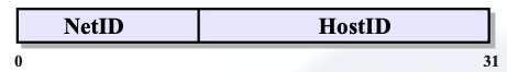
2.1 NetID & HostID
IP Divides the address in two parts to implement the network addressing plan:
- Devices with a common NetID are said to be in the same IP network.
- Devices in different IP networks must have different NetIDs.
- The portion of the address that identifies a particular device on the network is called the HostID.
For now we will consider that the address division is 24/8: 24 bits for NetID and 8 bits for the HostID.
For example if we have the IP address 192.168.0.1:
- NetID: 192.168.0 (24 bits)
- HostID: 1 (8 bits)
Note: There are some addresses that are reserved in each Network that depend on the HostID.
- If the HostID = 0s it is reserved for the network address.
- If the HostID = 1s it is reserved for the broadcast address.
So in our example, 192.168.0.0 would be the network address, and 192.168.0.255 would be the broadcast address.
But how do we separate this addresses between them, you may ask?
The answer is with the devices we all need at home if we want to connect to the Internet. Routers are the ones who separate the different IP networks.
And this is how we get to understand the next step.
3. Routing
Routing is the name we have given at the process that routers do when interconnecting different data link layers.
Routers transfer IP packets from one DLL to another, but frames are not transferred.
When doing IP Routing, what we are doing is searching all over the Internet the destination device we want to reach.
To do that, IP users provide the destination IP address or name to the router, and this one tries to find where it is located, to transmit data between the two hosts.
However, IP does not guarantee a reliable delivery. It provides a best effort host to host service, as it uses a hop by hop routing mechanism.
This means that each packet is sent from one router (hop) to another one (next hop) in the path.
By using this mechanism, we achieve a higher scalability than with Ethernet for various reasons:
- Routing tables group addresses: The amount of information that a router needs to keep is proportional to the number of networks in the Internet, not the number of devices.
- Routers filter Layer 2 traffic: they efficiently forward (route) packets between data link networks.
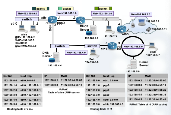
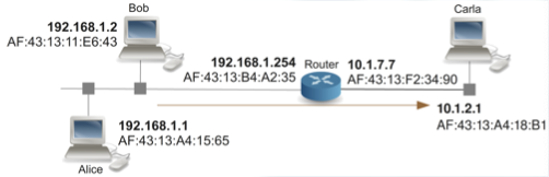
Example of IP Routing:
4. Internet Applications
Many protocols over the Internet use the IP network with a client/server model.
But what is a client/server model exactly?
- Servers are processes or network daemons that are running continuously in the background.
- Clients are the ones who initiate the communication with servers.
- Clients must know the address of the server (but not necessarily otherwise when the communication is initiated).
When we initiate processes, the address must be composed of 3 parameters:
IP address, transport protocol and port.
The transport protocols (L4) provide multiplexing identifiers for their users. This multiplexing IDs have a size of 16 bits and they are called ports.
There are two transport protocols: TCP and UDP.
- User Datagram Protocol (UDP)
- Simplest transport protocol
- Message-oriented
- Each UDP datagram is encapsulated in a IP datagram
- UDP only offers multiplexing and checksum for discarding wrong data
- For multiplexing it uses the source and destination ports
- Transport Control Protocol (TCP)
- TCP provides full-duplex communication, and encapsulates its data over IP datagrams
- Connection-oriented (there is a handshake of three messages before data can be sent)
- The communication is managed as a data flow (not message-oriented)
- TCP is reliable, as it adds support to detect errors or lost data and to trigger retransmission until the data is correctly and completely received
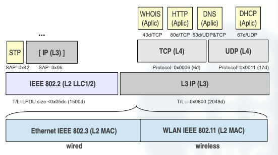
Over this protocols, we do have the next Layer in the OSI model, which is the Application Layer.
Here we can use the different applications that exist over the Transport protocol layer, like WHOIS, HTTP, DNS, DHCP…
A nice recap of what we’ve seen so far would be the following image:
5. Classful IP
Let’s get back to the backbone of this article.
We’ve seen before that IP addresses are divided in NetID and HostID, to identify either the network the device is in, and the exact device that we want to establish a communication with.
Let’s now see how does IP solve the problem of finding who is each device in their network.
5.1 Address Resolution Protocol (ARP)
When we want to find who is exactly each device in our network, we use the ARP protocol.
ARP is a request/response protocol for the dynamic resolution of the mapping @IP-@MAC.
It uses two messages ARP-request and ARP-reply, both encapsulated in MAC frames.
To figure out the MAC address associated with a certain IP address, ARP does the following process:
- The sender sends an
ARP-requestto broadcast (ff:ff:ff:ff:ff:ff) - This request contains the IP address of the host whose MAC address we want to know.
- The device in the L2 network that has been configured with the IP requested, sends an
ARP-reply. - This
ARP-replyis unicast and it has as destination MAC the @MAC of the station that sent theARP-request. - Now, both sender and receiver know the L2 and L3 address mappings of each other.
ARP Caché:
Since Broadcasting is very costly, a local file is used to store the bindings learned with ARP.
With this caché, we can handle future requests faster or more efficiently.
However, we need a mechanism to update this cache, because it cannot store all the addresses forever, as some addresses turn obsolete.
This mechanism is a timeout, or Time To Live (TTL). When the TTL expires, the binding is removed from the ARP cache.
TTL can be manually configured.
In a Lunix OS, we can use several commands to view the ARP cache and to re-configure it, for example:
arp -n 						#View the arp cache
arp del 192.168.1.2 		#Delete mapping
arping 192.168.1.2			#ARP request
ifconfig 					#View interfaces configuration
ifconfig eth0 192.168.1.1	#Configure IP to eth0
arp set 192.168.1.2 00:23:ae:1c:51:29 [temp] #sets a temporal mapping
So far, we’ve learned how IP packets are exchanged between devices that are on the same data link.
But we want to exchange packets between devices that are not in the same data link.
So, how can we know that a device is connected to a certain data link?
The answer is the 2 parts of the IPv4 addresses, NetID and HostID.
As you know, the devices that share the same data link, must have the same NetID, so forth, a device only needs to check if the destination @IP has the same NetID to know if the receiver is in the same data link of the sender, or on another one.
Now we need to introduce a new concept to understand how to route the packets to the correct data link.
Classes of Addresses.
Class-A Addresses
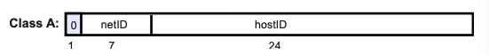
- 8/24
- NetID: w → 0–127
- HostID: x.y.z
- Number of Networks: 2⁷ = 128 networks
- Number of addresses per network = 2²⁴ = 16.777.216 addresses
Class-B Addresses
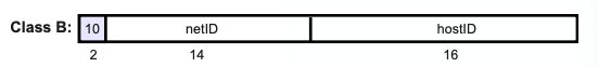
- 16/16
- NetID: w.x. → 128–191
- HostID: y.z
- Number of Networks: 2¹⁴ = 16384 Class B networks
- Number of addresses per network = 2¹⁶ = 65536 addresses
- Private addresses from 172.16.0.0 to 172.31.0.0
Class-C Addresses
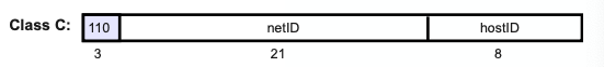
- 24/8
- NetID: w.x.y → 192–223
- HostID: z
- Number of networks: 2²¹ = 2097152 Class C networks
- Number of addresses per network: 2⁸ = 256 addresses
- Private network addresses from 192.168.0.0 to 192.168.255.0
Class-D and Class-E
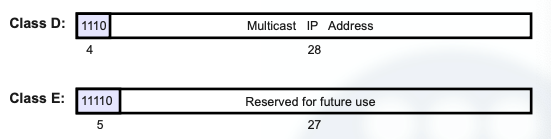
Class D:
- Used for group communications, or multicast.
- The first byte of class D goes from 224 to 238.
Class E: the whole addressing of this class is reserved for future use
6. Types of Delivery
Great, so now you know how are addresses routed to get to their destination. To classify in an easier way the routing of datagrams, we introduce two more concepts called
- Direct Delivery
- Indirect Delivery
6.1 Direct Delivery
We use direct delivery when either sender and receiver are physically connected to the same L2 network.
This means the destination IP address has the same NetID than the IP source address.
Direct deliveries do not require intermediaries (routers).
We use the ARP cache or the ARP protocol to find out the destination @MAC, which is the only missing parameter to build the MAC frame.
6.2 Indirect Delivery
The next step is to learn how to make indirect deliveries, which as you may have guessed, are the types of datagram deliveries that are made from one device that is connected to a certain network, to another device that is connected in a different network.
For this purpose, we use routing tables and an intermediate device: an IP router (IP gateway).
A routing table is a local table (each host or router has one) that is consulted to find the parameters of the next hop, where the packets must be forwarded.
In Unix-like systems you can view the routing table with the command route -n.
The first thing we need to observe in the previous example, is that our router has two NICs and also two IP addresses configured, one to each NIC.
In general, routing tables contain at least the following entries:
- Destination network address
- Output NIC
- Next Hop (The @IP of the next hop)
Let’s see an example of the previous picture, but with it’s corresponding routing tables from each host:
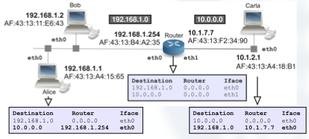
So, once you’ve understood the routing tables, and how they are configured into each host, it’s much easier to get how indirect deliveries work.
IP routing is performed hop by hop: routers/hosts only take care of finding the parameters of the next device where to forward the packet.
So for this purpose, the routing table provides us with the @IP of the next hop, which has to be directly reachable.
6.3 ICMP
As you may imagine, indirect deliveries have more problems than direct ones.
That’s why ICMP was implemented. This protocol is called Internet Control Message Protocol (ICMP), and its purpose is testing and finding anomalies in networks.
Let’s imagine that a packet arrives to a router that hasn’t got any routing entry for the destination.
In this situation, ICMP defines a message that the routers can send to the source indicating why the packet did not arrive to its destination and why it has been discarded.
Then we can find another better route to send our packet through, or try to solve the problem.
If you ever try to do networking tasks, you’ll find ICMP very useful to test if the network is working or not, and you’ll get very used to the following messages:
- echo-request (ping)
- echo-reply (pong)
7. Classless IP
The previously explained IP (classful IP) has two big problems:
- Address Exhaustion
- The class structure is not efficient
- An institution or company that wants to build an IP network of 6 hosts, needs an entire C-class address, which will result in 248 unused addresses. That scales even worse when we need more addresses, as if we need to connect 300 hosts, we would have to ask for a B-class, and would end up in 16082 unused addresses.
- Slow Routing
- Classful addressing generates large and unmanageable routing tables, as we need one entry in the routing table per class.
- This was critical for the routers of the Internet Backbone that have to route packets at high speeds.
That’s when people realized that Internet was “dying of success”, and something had to be done.
The proposed solutions for this problems were the following ones:
- Subnetting / Supernetting
- CIDR (Classless Inter Domain Routing) with geographical allocation of addresses.
- Dynamic NAT for using less public addresses.
- DHCP for reusing IP addresses
Moreover, IPv6 is another solution, which we will not cover in this article, but also solves all the previous problems and has an even better scalability.
It’s main difference with IPv4 is the address space, which goes from 32-bit to 128-bit addresses.
7.1 Subnetting
When dealing the previously seen problems, a new concept appeared: Net masks.
Net masks allow us to split networks in many different parts, and also group them in bigger ones.
In particular, a Subnet is a network smaller than the original class.
To indicate that a certain network has a net mask, we can use different notations, however the most common one is the CIDR notation.
This notation is exactly like this: @IP/X where X is a decimal value indication the number of 1s of the network mask.
Eg 1: 147.83.0.0/16 is a network number of a class B network.
Eg 2: 192.168.1.3/24 is an IP address of a host in a class C network.
Let’s see an example of a Class C Division (the most common ones you’ll see)
We want to divide the private Class C 192.168.1.0, which has room for 256 addresses, into 2 different subnets with 128 addresses each.
Actually, subtracting the network address and the broadcast address from each one of them, we would end up with 2 networks of 126 hosts each.
To do so, we need extend the network part in one bit.
Now I’ll show you my way of calculating how to identify the netmask we need to divide our bigger networks.
As we know in Class C addresses, we have 256 free addresses, which is 2⁸.
This means we have 8 bits for the HostID (256 hosts), and 24 bits for the NetID.
If we add one extra bit to the NetID, we end up with 25 bits for the NetID and 7 bits for the HostID.
If we calculate how many hosts we can have with 7 bits, we just do 2⁷ = 128.
Exactly the number of hosts we needed!
So now, we can see our 2 subnets, divided thanks to our mask:
- The first one goes from 192.168.1.0/25 → 192.168.1.127/25
- The second one goes from 192.168.1.128/25 → 192.168.1.255/25
Masks are also used in the routing tables of routers that are “aware of subnetting”.
Let’s see an example to understand it better:
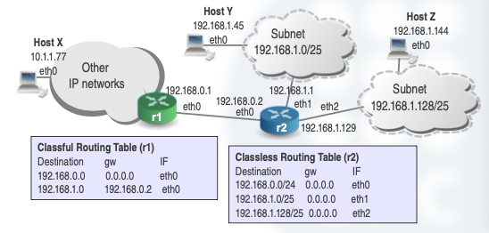
Notice that we might have an IP network in which we have classful routers and classless routers (r1 and r2).
Outside the subnets, the routers can still use classful routing.
In our example, router 1 still sees 192.168.1.0 as a class C network address, and uses a classful routing table.
However, the internal router (2), is aware of subnetting and it is able to differentiate between the two subnetworks.
In this case, to properly route IP packets to each subnet, the router 2 uses a classless routing table, which includes masks for correctly interpreting IP network numbers.
Until now, we have been using a type of subnetting called FLSM (Fixed Length Subnet Mask), which as it name indicates, it creates fixed subnets, all of them have the same number of hosts.
But what happens if we want to divide a /24 network (256 addresses) into 3 subnets, one with 120 hosts, and the other 2 with 60 hosts each one?
Here is when VLSM (Variable Length Subnet Mask) comes into play.
To divide networks into smaller ones, we must always start with the biggest one we want to create. So in this case, we would first need to assign 7 bits for the HostID (120 hosts needs at least 128 addresses, 2⁷) and then we would need at least 2 extra bits to differentiate the 3 networks between them.
So we would end up with 9 bits needed for this network, which makes it imposible for a /24 network to divide it when using FLSM. We would need at least a /23 network, and the subnets would be like this:
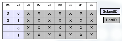
We can see that we need 9 bits to divide the 3 networks (which will actually create 4 networks, and one of them will be redundant).
- SubnetID == 00 → 10.0.0.0 to 10.0.0.127 (/25)
- SubnetID == 01 → 10.0.0.128 to 10.0.0.255 (/25)
- SubnetID == 10 → 10.0.1.0 to 10.0.1.127 (/25)
- SubnetID == 11 → 10.0.1.128 to 10.0.1.255 (/25)
On the other hand, if we used VLSM, we could have adapted our network with just a /24 mask, as the 8th bit would actually differentiate the bigger network from the smaller ones, and the 7th one would differentiate the two small networks between them.
- SubnetID == 0 → 10.0.0.0 to 10.0.0.127 (/25)
- SubnetID == 10 → 10.0.0.128 to 10.0.0.191 (/26)
- SubnetID == 11 → 10.0.0.192 to 10.0.0.255 (/26)
This way we would have room for all the hosts we need, and we would not be occupying redundant space on the network.
7.2 Supernetting
As you may imagine, supernetting is the opposite of subnetting.
Grouping smaller networks into a bigger one.
Let’s assume that we need an address block for a network composed of 1000 hosts.
A class C network provides only 254 addresses, so it is not enough.
We could ask for a class B address, but we would drop 2¹⁶ — 2–1000 = 64534 addresses.
So, the solution would be using multiple class C networks.
A network with 1000 hosts needs at least 4 classes C.
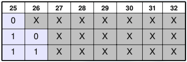
Example:
200.45.64.0 → 11001000 . 00101101 . 010000 00 . 00000000
200.45.65.0 → 11001000 . 00101101 . 010000 01 . 00000000
200.45.66.0 → 11001000 . 00101101 . 010000 10 . 00000000
200.45.67.0 → 11001000 . 00101101 . 010000 11 . 00000000
See that we need at least 10 bits to differentiate the networks, which brings us to a /22 mask to group them all into the same bigger network.
Finally, it is worth to remark that Internet routers use this idea of classless routing, and so fort, Internet routers abandoned the old scheme of old IP classes.
8. CIDR
Classless Inter-Domain Routing (CIDR) means that Internet routers do not follow the classes scheme.
It implies that we can aggregate many networks and route them with just one entry to be effective.
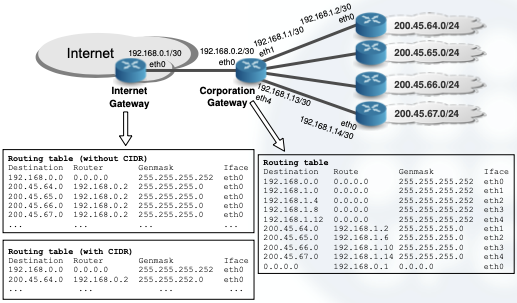
CIDR is suitable for reducing the growth of routing tables and for providing efficient routing in the backbone Internet routers.
It reduces the number of table entries as we can aggregate many blocks of addresses and route according to these supernets.
With few entries, the processing time due routing is decreased.
After this idea came into play, classes made no sense anymore inside the Internet, and nowadays the routing tables of the Internet routers are also classless.
However CIDR, supernetting and subnetting are all compatible.
Their combined usage provides effective management of address allocation and routing tables.
- Edge routers use long prefixes for their subnets and short prefixes to describe other networks.
- Core routers in the Internet backbone try to route packets with the shortest prefix possible (biggest possible supernet).
We are getting to the end of this article. I hope you found what you were looking for, and wish that you now have a better understanding of the Internet Protocol, and how do we connect and send packets between devices, even if they share the same network, or if they are in another part of the world.
This is the second episode of a complete series that will guide you through the Internet Basics, so in case you want to improve your digital knowledge, and have a solid understanding of how does the internet work, keep tuned in to my profile as I’ll keep posting articles about this topics.
Leave a clap if you enjoyed this post, you’ll support my work and help me keep myself motivated to write more! Knowledge is power!