Internet Educational Series #1: Ethernet, Switching & VLANs
How does the Internet work? If you ever had this question popping up in your head, you’ve landed in the right place.
Hello dear reader! And welcome to my Internet Educational Series.
Here you’ll learn all the basics from the Internet, how does it work, why does it work, the protocols used, and many many more you’ll get to discover as you read my articles.
I hope you like them, and enjoy them as much as I’m doing when writing them.
All right, let’s get into it!
I’ll start from the beginning, trying to cover all aspects of how the Internet evolved to reach what it is nowadays.
1. History
The internet history itself starts a long time ago, with an invention called ARPANET with military purposes as many things have done during history, however, my articles won’t cover this part, they are solely focused on the actual and “true” internet as we know it.
As you may imagine, the internet did not start as the wireless network it is nowadays. At the start, communications were made by cable (most of them still are), and the first technology that was invented aimed to propagate information from one place to another, was called ETHERNET.
The first Ethernet was designed in 1973 by Bob Metcalfe in Xerox Corporation’s Palo Alto laboratory.
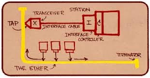
This first version was able to operate at 3Mbps over a shared coaxial cable using CSMA-CD.
Metcalfe convinced DEC, Intel and Xerox (“DIX”, Digital Intel and Xerox) to work together to promote Ethernet as a standard. The first DIX standard draft was published on September 30, 1980 by the Institute of Electrical and Electronics Engineers (IEEE) under the standard 802.3.
The DIX standard specified the MAC layer of a 10Mbps local area network called Ethernet.
2. The Ethernet Frame
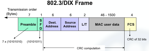
Let’s see the general design of IEEE 802.3/DIX frame:
- The medium is a coaxial cable (a single link bus)
- A Manchester line code is used to transmit each symbol.
- The transmission of frames is asynchronous.
- Multiple stations are allowed to be connected to the link (multi-point) and the MA (medium access) is based on CSMA-CD.
- Each station is identified by a MAC address of 6 bytes (48 bits).
- There is a 2-byte (16 bits) field for multiplexing MAC users.
As mentioned, the transmission over the coaxial was asynchronous and used the Manchester line coding, thus the preamble and SDF were necessary to synchronize the receiver.
- Mac Addresses
- Mac addresses are formed by 48 bits, and it serves as Hardware address, physical address, Ethernet address or layer 2 address.
- It is usually expressed in Hexadecimal (12:34:56:78:9A:BC)
- The standard transmission order sends the Most Significant Byte (MSB) first, and inside this byte the least significant bit (lsb) first.
- For example, the MSB of 12:34:56:78:9A:BC is 12. Which in binary, 12 is 00010010, and we start transmitting the lsb: 01001000…
- The meaning of the lsb and MSB is:
- 0: individual address (unicast)
- 1: Group address (Multicast) I’ll explain more in depth what is Multicast in a future article
- If we find that all 48 bits are 1 (FF:FF:FF:FF:FF:FF) it means that we are transmitting to broadcast.
- Mac User Data
The maximum user data that can be carried in a L2 frame is called the Maximum Transfer Unit (MTU).
For the Ethernet, the MTU is 1500 bytes. The minimum quantity of bytes of user data is 46 bytes. In case our data is less than 46 bytes, we have to pad the data by adding zeros at the end (zero padding).
Notice that the MAC user must include a length field in its PDU to distinguish its data from the padding.
- Frame Check
This field is a Cyclical Redundancy Check (CRC) of 4 bytes (32 bits).
The CRC is used to detect incorrect frames.
The CRC value calculated by the destination, might not match the FCS field value f the frame for 2 reasons:
- Errors
- Collisions
It is important to know that 802.3 receivers DO NOT implement error control, but erroneous frames are silently discarded.
In case we want to manage errors at layer 2, we have to use the optional LLC sublayer, which is defined in the standard IEEE 802.2 (We’ll se more about LLC below).
The MAC layer of the Ethernet MUST be the one who manage collisions.
3. How do we connect senders & receivers? With a Twisted Pair
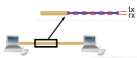
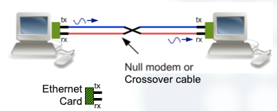
In the above pictures we can see how two stations are connected via Ethernet with twisted pairs crossover cables.
But what to do with more stations? We use HUBS.
Let’s see some examples to understand better how to connect multiple stations:
3 stations:
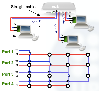
As we can see, the TX cable from the 1st station is connected to RX entries from the other ones.
And we can even connect hubs with other hubs!
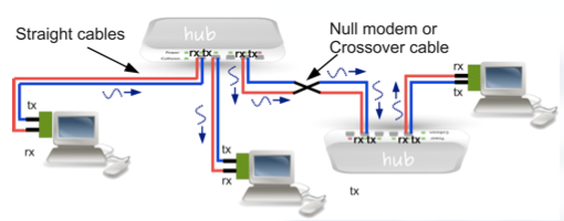
This way, when hubs are connected between them, we do just have to crossover the cables, and we can send information to every station on the network.
However, when transmitting with hubs, collisions appear, and this led engineers to think of a better way to connect stations between them.
4. Full-Duplex Ethernet
The BRIDGE concept
When trying to connect multiple stations, many collisions were found, and to try to avoid them, engineers came with an idea.
The idea was to separate collision domains.
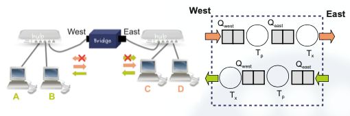
However, this broke the concept of having one MAC per link, thus developers had to develop a data link layer network capable of managing different links.
Let’s see some important features from the Bridges:
- A bridge is not a physical device like the hub. The bridge processes the frames, and analyses the destination address of each frame.
- If the destination MAC address belongs to the same collision domain of the incoming port, the bridge drops the frame.
- If the destination MAC address belongs to the other collision domains, the bridge sends the frame through the other port.
But how does the bridge know which MAC address belongs to each collision domain?
The answer is called MAC LEARNING, which is an algorithm used by the Ethernet.
The bridge learns mapping between MAC addresses and collision domains by observing the source address of each received frame.
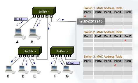
Let’s see an example:
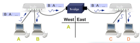
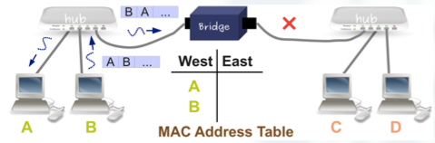
- When A sent the frame, the bridge learned that the MAC of A is in the west collision domain.
- Later when B sends a frame to A, this frame is not transmitted to the East port because the bridge knows that the MAC of A is in the west domain.
- Notice that when B sends the frame to A, the bridge learns that B is also in the west collision domain.
The MAC learning algorithm runs as an uncoordinated process in each bridge, in the sense that the algorithm does not require any coordination with other network devices.
This makes it not scalable for big networks, as a global coordinated process is necessary for such networks.
The Switch Concept
When we extend the bridge concept to a device with more than two ports, we arrive to the concept of SWITCHING.
Simply stated, a switch is a multi-port bridge.
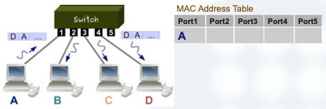
When the switch receives a frame with an unknown MAC, it maps the MAC to the port and sends the frame for all its ports except through the incoming port.
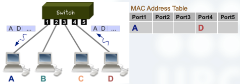
When a MAC is learned, the frame is sent only to the associated port.
Let’s see what happens when D responds to A sending a new frame:
Implementation of a Switch
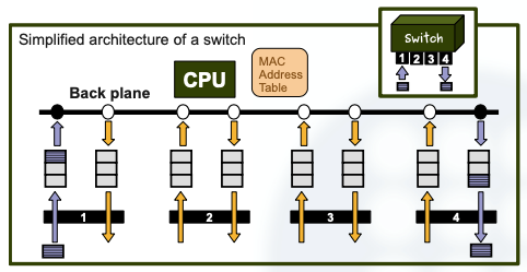
In this section I’ll describe a possible simplified implementation of a switch with 4 ports full-duplex of 10Mbps:
- Queues are used in each port for buffering incoming and outgoing frames.
- The bus we need has to be at least a shared bus of 40 Mbps.
- This bus is called a ”back plane”.
- We manage the back plane bus with TDM deterministic multiplexing using four time slots.
- Using the shared bus, each port is switched with another port (or ports) at a rate of 40 Mbps but only gets 1 slot each 4 time slots (which yields the 10Mbps transmission rate).
- Notice that with this design, finally we obtain a switch of 4 ports without collisions, at a rate of 10Mbps, that can be used for a full-duplex communication.
Data Link Layer Networks
The next step is to build a “data link layer network” by interconnecting several switches.
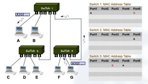
We can see that the same algorithm is applied to the data link layer network.
Once all the MAC addresses have been learned, broadcasting is not used anymore and the frames are forwarded using the MAC address table.
This way there are no collisions because the frames are always transmitted “alone”.
5. Broadcast Effects
Broadcast as you may know is the act of sending a frame to EVERYONE in the network. Not only to all switches but to all stations connected to the switches.
The broadcast MAC address is FF:FF:FF:FF:FF.
When a switch receives a frame with a broadcast address, it sends the frame through all its port except through the incoming one, idem as in MAC learning.
However, broadcast should not be overused as it can cause buffer overflows. It is a limiting factor because it generates traffic in the reception of all the ports of the switch.
6. Redundancy
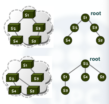
One of the limitations of the MAC learning algorithm is that it generates transmission loops in redundant physical topologies.
A redundant topology provides several paths for connecting a source with a destination. It might be interesting for providing a reliable switching service; in case a path is unavailable, we can use another one.
Spanning Trees
A solution for fixing L2 switching loops is to generate a logical tree. These logical trees are called “spanning trees” and they avoid possible switching loops.
A protocol called Spanning Tree Protocol (STP) is used to dynamically build the spanning tree.
If switching path becomes unavailable, the STP dynamically generates another spanning tree.
7. Final Remarks
Modern switches use several physical signals to auto-negotiate certain aspects of the communication.
- A physical signal allows a station to automatically detect if the device is a switch or a hub.
- In connections between switches, physical signals allow switches to detect each other and negotiate which one is going to be the null modem port.
- Stations and switches also negotiate transmission rates.
- The standard of Ethernet at 100Mbps is called “Fast Ethernet”.
- In Fast Ethernet a pair of twisted wires is used for each direction.
Well, we are getting to the end of this article. I hope you found what you were looking for, and wish that you now have a better understanding of Ethernet protocols, and how do we connect networks using switches.
This is just the first episode of a complete series that will guide you through the Internet Basics, so in case you want to improve your digital knowledge, and have a solid understanding of how does the internet work, keep tuned in to my profile as I’ll keep posting articles about this topics.
Leave a clap if you enjoyed this post, you’ll support my work and help me keep myself motivated to write more! Knowledge is power!